Static and dynamic connectors
When creating shapes in the drawing it is needed to use the connector. These lines allow to link two shapes with each other, can have different types and arrows, color and thickness. Essential for these connectors is a specific connection point on the edge of shapes. we are talking about the so-called Connecting points. These points are usually on the center of lines, or can be created anywhere in the area. You can also connect the isolated point.
This article discusses the types of connectors – the type of connection between the two shapes. The connector may adapt themselves to the new position when you move shapes and it needs to find a shorter route, or the connection is still freezed in the same Connecting points.
Dynamic connectors
The connection between the shapes exists, but the connection points are subject to change. When you move a shape within a drawing to another location, the connector may be adapted to the new position and change its shape, length and connection points. Visio is trying to find the most effective “way”.
Creating dynamic connectors
- On the Home tab, activate the Connector icon.
- Move mouse inside of the shape to display a red border around it.
- Click and drag to another shape again in his inner part and release the mouse button.
Red box when creating a connector means that Visio itself decide on the best location for a connection point and it may change when moving shapes.
Static connectors
If we want to make the connection between the shapes to be still at the same point after the change of position of the shapes in the drawing, you must set them manually between specific connection points.
Creating static connectors
- On the Home tab, activate the Connector icon.
- Hover mouse over the edge of the shape until you see the red spot (usually in the middle of the side).
- Click and drag to another shape again to some red spots on its outline.
Red spot when creating a connector means that we determine the specific connection points from which the connector leads, his position when moving patterns does not change.
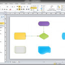
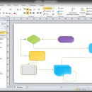
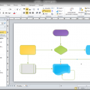
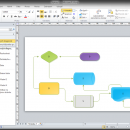
The picture shows a shape before and after the change of position. Shape marked “S” are associated with static connectors, marked “D” are linked dynamically with each other.
The connection type between the shapes can be combined, one end of the connector can be linked dynamically and the other statically. When creating a connector is the key locations and dragging the mouse between shapes – inside or at connecting points.
Connector settings
The connector can be edited after creation. Again, it is possible to change the connections between the connection points by drag the connector edge.
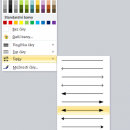
To format the connector is designed the Home tab> Line option.
Weight … here we set the weight of the connector
Dashes … here we set the line type, whether it is solid or dashed etc.
Arrows … here we set the direction or end arrows on the edge of connector
Line options … detailed setting for formatting connector types including rounding, when using the curved connector
If this guide has helped you, become a fan on Facebook and recommend this site to your friends, it can be useful for them too



Leave a Comment